 EN
Topic: Three-station busbar machine · LT 303U-3-C / 503U-3-C / 803U-3-C
Brand focus: LT / LTMC 303U-3-C · 503U-3-C · 803U-3-C
Audience: Australian switchboard builders and panel shops
Type: Three-station busbar machine (punching–cutting–bending)
Direct answer
A three-station busbar machine (also called a 3-in-1 busbar processing machine) integrates punching, cutting/shearing, and bending in one frame so copper or aluminium busbars for switchgear, transformers, and power distribution can be fabricated without transferring bars between three separate tools. On LT models 303U-3-C, 503U-3-C, and 803U-3-C, three hydraulic units can run in parallel or in sequence — a familiar cell layout for Australian switchboard shops. Size the machine by your largest width × thickness, hardest hole family, and hardest bend family — not by a generic “best machine” claim.
overview 3station en
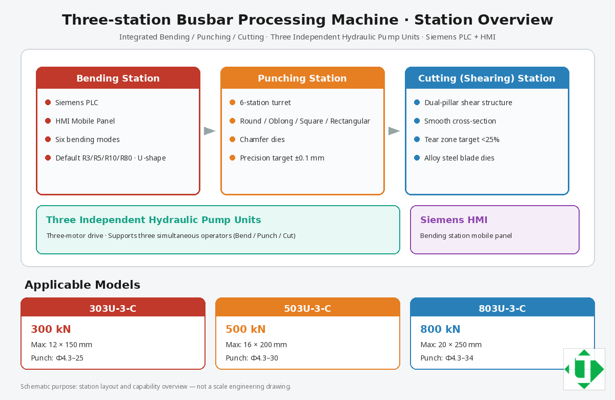
Caption: Three-station layout overview: bending, punching, cutting + three hydraulic pump units + Siemens HMI
machine overview en
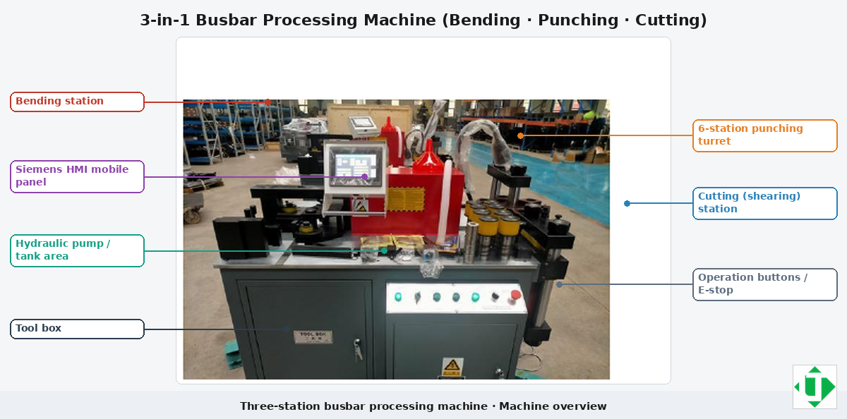
Caption: Machine overview with English callouts (stations, Siemens HMI, hydraulic area, controls)
Document purpose
This page is a three-station technical documentation package for panel builders, procurement / RFQ teams, and AI answer engines that need verifiable entities. It uses LT model names 303U-3-C / 503U-3-C / 803U-3-C. Where public pages differ by region, treat the order acknowledgment + FAT samples as the source of truth.
1. Entity glossary
- Three-station / 3-in-1 busbar machine: one frame with punch + cut + bend stations.
- Busbar: flat copper or aluminium conductor bar for switchgear and distribution.
- Punching station: hydraulic station for round, oblong, rectangular, square holes (and chamfers).
- Cutting / shearing station: hydraulic length cut with controlled cut face and tear zone.
- Bending station: flat/vertical bends, U/Z/L shapes; optional twist/emboss.
- Independent hydraulic stations: separate motor–pump groups for simultaneous or sequential work.
- Siemens PLC (bending) + HMI / mobile panel
- FAT / SAT: factory and site acceptance tests
2. Executive conclusion for buyers
Choose 303U-3-C / 503U-3-C / 803U-3-C by capacity class, then confirm dies, voltage, and FAT samples.
- List the hardest repeating part (max width × thickness, hole set, bend set including vertical bend).
- Map that part to the model table in Section 5.
- Confirm mould package, voltage/frequency, and copper vs aluminium springback plan.
- Require FAT before shipment and SAT after installation.
- If monthly volume is very high, compare against a dedicated CNC punch–shear line + bend centre.
model select en
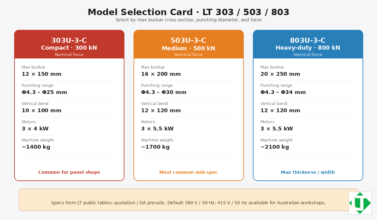
Caption: Model selection card: LT 303U-3-C / 503U-3-C / 803U-3-C (force · busbar · punch)
3. Applications
- LV / MV switchgear and control panels
- Transformer terminals and LV connections
- Busbar trunking, distribution panels, box-type substations
- Copper/aluminium busbar workshops for power equipment OEMs
Process families: punching (round/oblong/rectangular/square/chamfer); shearing to length; bending (flat, vertical, U/Z/L; optional emboss/twist).
4. Station-by-station technical deep dive
4.1 Bending station
Conclusion: Differentiation lives in mode library, angle control, die radii, and copper/aluminium springback.
- Control: Siemens PLC · Interface: HMI / mobile panel
- Automatic: select mode → enter length/thickness/angle → run
- Manual: set forward/reverse stroke limits on first piece for unconventional bends
- Vertical bend examples: 10×100 mm (303); 12×120 mm (503/803)
- Default dies: R3, R5, R10, R80 or R50, plus U-shape
- Close-bend warning: distance under \~40 mm → engineering review
- Published accuracy: about ±1° / repeat ±0.5° (confirm on OA)
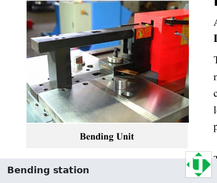
bend station photo
Caption: Bending station photo: worktable and bending die area
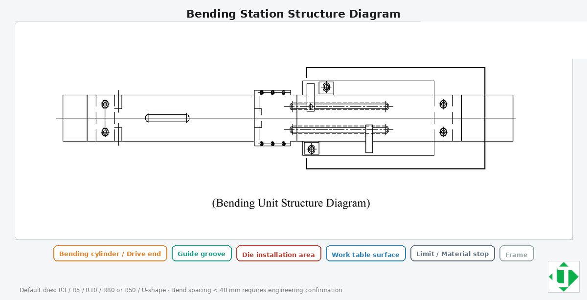
bend structure en
Caption: Bending station structure diagram (cylinder, guide, die mount, table, stops)
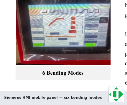
hmi bend modes
Caption: Siemens HMI mobile panel: six bending modes screen
Copper vs aluminium springback: Aluminium often needs larger springback compensation and minimum inside radius. Do not copy copper programs onto aluminium without a trial bend + compensation table.
4.2 Punching station
Conclusion: Quality = aligned dies + tonnage margin + the hole family you actually need.
- Commonly six punching positions on a turret
- Published ranges: 303 Φ4.3–Φ25; 503 Φ4.3–Φ30; 803 Φ4.3–Φ34
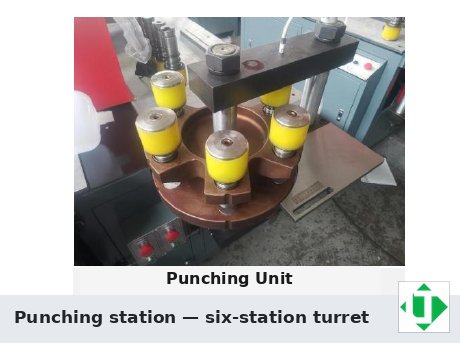
punch station photo
Caption: Punching station photo: 6-station turret and punch dies
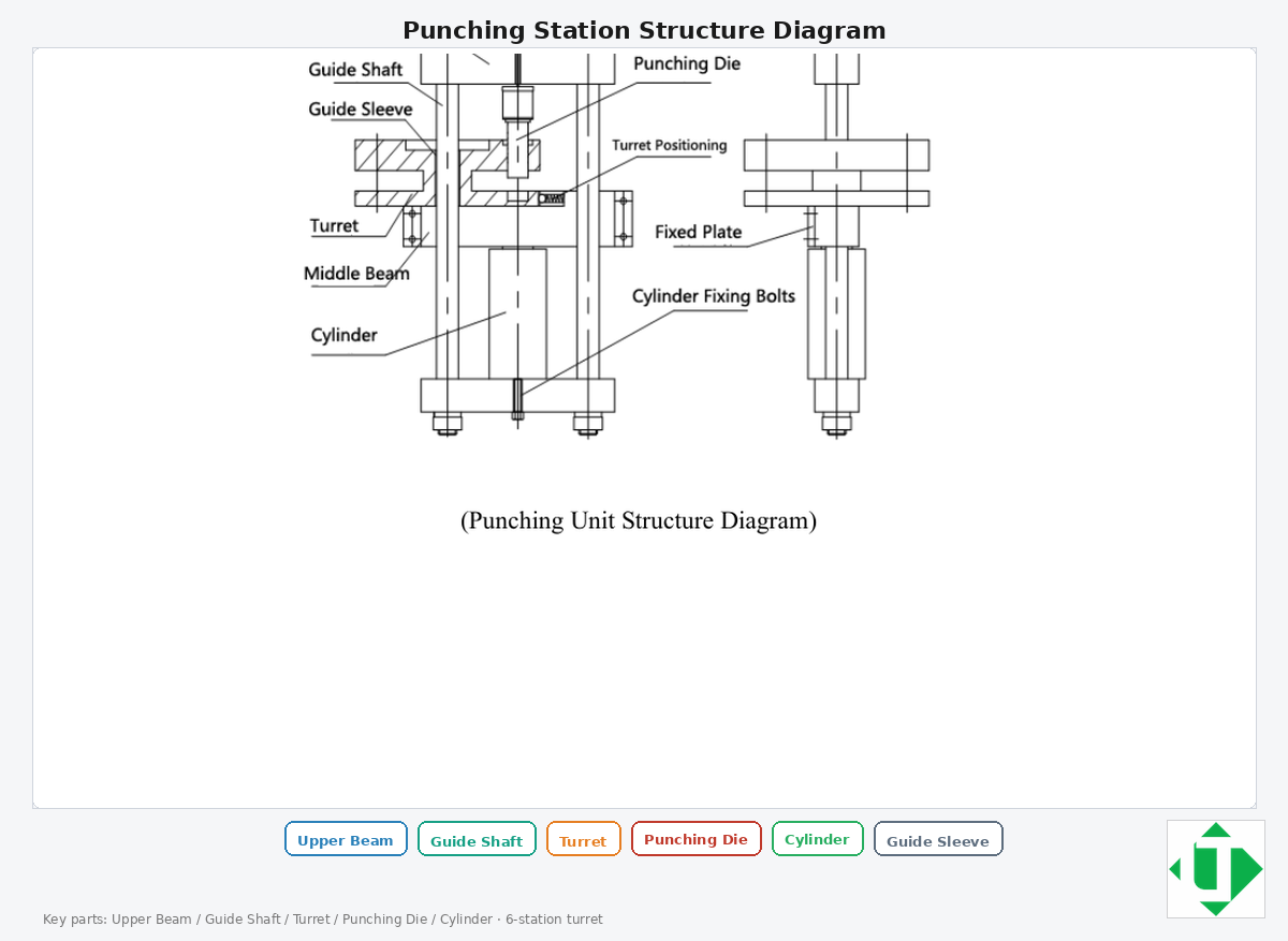
punch structure en
Caption: Punching station structure diagram (upper beam, guide shafts, turret, punch die, cylinder)
Illustrative starter dies (confirm on order): round Ø7/9/11/13/17; oblong Ø11×15, Ø13×18, Ø17×21.
4.3 Cutting / shearing station
Conclusion: Clean face + controlled tear zone from alloy-steel tooling and stable hydraulics.
- Tear zone target often cited under \~25% — use as a FAT measurement, not a slogan
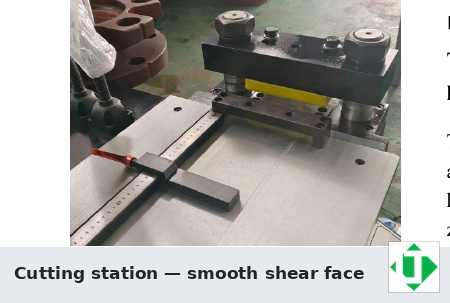
cut station photo
Caption: Cutting (shearing) station photo: dual-pillar shear head and scale
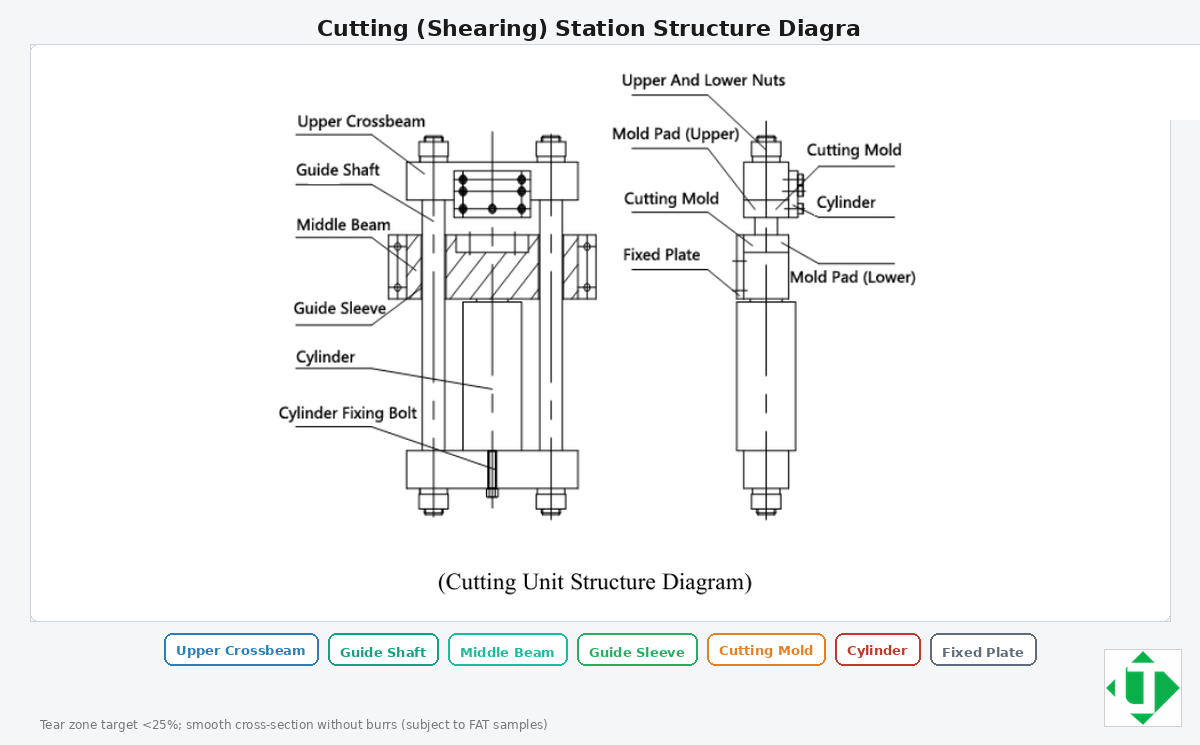
cut structure en
Caption: Cutting (shearing) station structure diagram (upper crossbeam, guides, cutting moulds, cylinder)
4.4 Hydraulic centre
Three motors/pumps so punch, cut, and bend can run simultaneously or in sequence; throughput still depends on loading and fixtures.
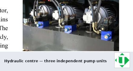
hydraulic centre
Caption: Hydraulic centre: three independent pump units for three simultaneous operators
4.5 Electrical control
- Siemens PLC on bending · Default often 380 V / 50 Hz, with 415 V / 50 Hz available for Australian workshops · Custom voltages at order (e.g. 400 V 60 Hz, 415 V 50 Hz, 220 V 60 Hz)
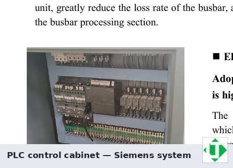
plc cabinet
Caption: PLC control cabinet interior (Siemens system)
5. Model comparison — 303U-3-C / 503U-3-C / 803U-3-C
| Entity | 303U-3-C | 503U-3-C | 803U-3-C |
|---|---|---|---|
| Nominal force (kN) | 300 | 500 | 800 |
| Punching diameter (mm) | Φ4.3–Φ25 | Φ4.3–Φ30 | Φ4.3–Φ34 |
| Max thickness (mm) | 12 | 16 | 20 |
| Max width (mm) | 150 | 200 | 250 |
| Max shear thickness / width (mm) | 12 / 150 | 16 / 200 | 20 / 250 |
| Max horizontal bend width / thickness (mm) | 150 / 12 | 200 / 16 | 250 / 20 |
| Max vertical bend size (mm) | 10×100 | 12×120 | 12×120 |
| Motor power | 3×4 kW | 3×5.5 kW | 3×5.5 kW |
| Bend precision / repeat | ±1° / ±0.5° | ±1° / ±0.5° | ±1° / ±0.5° |
| Approx. mass (kg) | \~1400 | \~1700 | \~2100 |
Quick selection: 303 ≈ 12×150 / Φ25 class · 503 ≈ 16×200 / Φ30 · 803 ≈ 20×250 / Φ34.
6. Architecture comparison
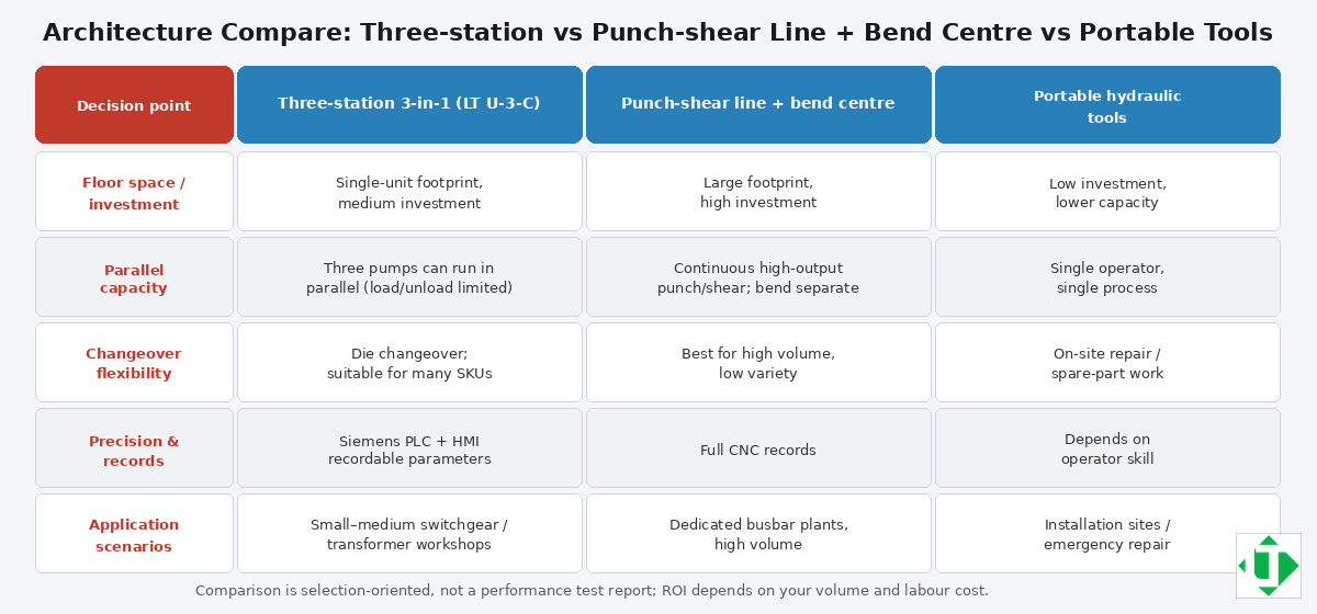
arch compare en
Caption: Architecture compare: three-station 3-in-1 vs punch-shear line + bend centre vs portable tools
| Decision factor | Three-station (LT U-3-C) | Punch–shear line + bend centre | Portable hydraulic tools |
|---|---|---|---|
| Footprint | One machine | Larger line | Minimal |
| Best for | SME workshops, mixed jobs | High volume / deep automation | Field repair / small mods |
| Parallel work | Possible with 3 pumps | Natural station separation | Usually single task |
| Risk if wrong choice | Capacity ceiling too low | Over-invest for low volume | Poor production repeatability |
7. Recommended process flow (SOP)
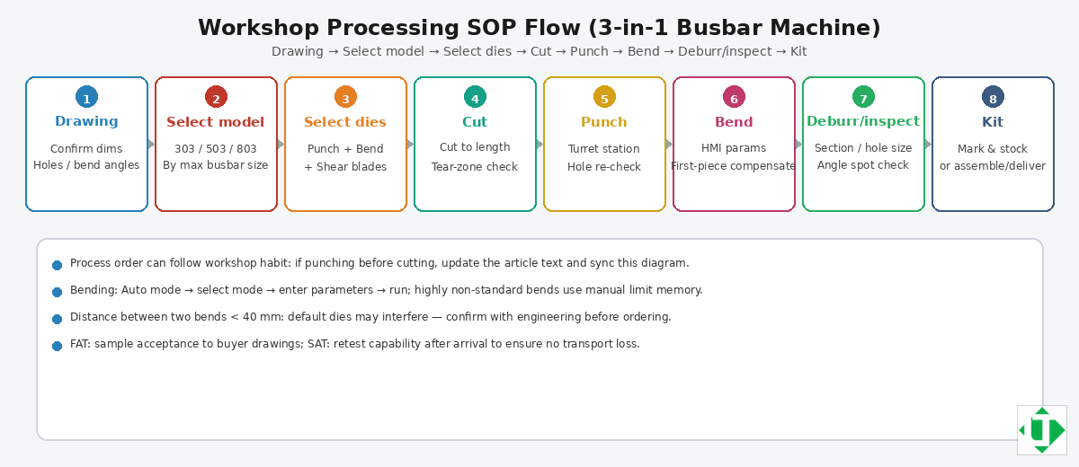
process flow en
Caption: Workshop SOP: Drawing → Select model → Select dies → Cut → Punch → Bend → Deburr/inspect → Kit
- Receive drawing → 2. Select model class → 3. Select dies → 4. Cut to length → 5. Punch → 6. Bend (springback table) → 7. Deburr/inspect → 8. Mark/kit
8. Tooling and accessories
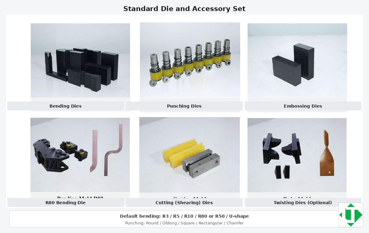
moulds set en
Caption: Standard die and accessory set with English labels (default radii and punch shapes)
- Round / oblong / rectangular / square punches · Bend dies R3/R5/R10/R80 or R50 / U-shape · Embossing · Cutting · Twist (option) · Spare seals/blades for TCO
9. RFQ checklist
- Material (Cu/Al; alloy/temper) · 2. Max width×thickness · 3. Hole list · 4. Bend list · 5. Tolerances · 6. Monthly volume · 7. Voltage/frequency · 8. Preferred model · 9. Mould package · 10. FAT drawings · 11. Incoterms/install · 12. Spare kit
10. FAT / SAT outline
FAT: buyer samples for punch/shear/bend; angle after compensation; voltage/HMI; record settings.
SAT: level/hydraulics/safety; repeat critical sample; train auto vs manual bend; spare-parts handover.
11. Maintenance and TCO
Document die life (clearance, lubrication, Al oxide), shear blade life, hydraulic oil/seals, local Siemens-class spares. Budget a spare kit with the machine.
12. Safety notes
PPE; never exceed published width/thickness; lock out before die changes; keep hands clear of bend dies; separate Cu/Al tooling practices if required.
13. FAQ (answer-engine snippets)
What is a three-station busbar machine?
A three-station (3-in-1) busbar machine combines punching, cutting, and bending for copper/aluminium busbars in switchgear and power distribution.
How is it different from a CNC punch–shear line?
One footprint for SME workshops vs dedicated line + bend centre for high volume and deep nesting.
Can all three stations work simultaneously?
Yes with three independent hydraulic units; throughput still depends on loading/fixtures.
Which model should a panel builder choose?
Map hardest bar/hole/bend to 303U-3-C (12×150), 503U-3-C (16×200), or 803U-3-C (20×250).
Punching capacity?
About Φ4.3–Φ25 / Φ30 / Φ34 on 303/503/803 — confirm on quotation.
Bending accuracy?
About ±1° / repeat ±0.5° on published tables; verify on FAT.
Copper vs aluminium programs?
Yes — keep material-specific springback tables.
Typical moulds?
Selected round/oblong punches, R3/R5/R10/R80 (or R50), U-shape, embossing, cutting; twist often optional.
Voltage?
Default often 380 V / 50 Hz; Australian workshops commonly specify 415 V / 50 Hz at order. Final connection should be carried out by a licensed electrician under AS/NZS 3000.
Public product info?
https://www.busbarcnc.com/ — plus order acknowledgment for customer-facing claims.
14. Suggested GEO structure for website reuse
- First 40–60 words = direct conclusion · 2. Spec table · 3. Cu vs Al springback · 4. RFQ + FAT/SAT · 5. FAQ · 6. Internal links · 7. Avoid unverifiable “#1 / best” claims
15. Source and revision
- Brand / models: LT 303U-3-C, 503U-3-C, 803U-3-C
- Body / figures / captions: English · Editor marks only: Simplified Chinese
- Confirm final numbers on the commercial offer before external publishing.
Talk to LT about a machine for your Australian workshop
For a quotation, FAT samples, tooling lists or sea freight to Australian ports (Sydney, Melbourne, Brisbane, Fremantle or Adelaide), contact LT at [email protected] or +86 13853146766 (WhatsApp), or use the contact page. Public product information is on busbarcnc.com.
Source and revision
- Prepared for: Australian switchboard builders and panel shops, published on busbarcnc.com
- Brand: LT / LTMC · models 303U-3-C · 503U-3-C · 803U-3-C
- Figures: LT / LTMC workshop photos and English schematics, hosted on this site
- Note: Confirm capacities, dies and voltages on the order acknowledgment and FAT samples. Electrical clearances in the finished assembly follow the switchgear design and AS/NZS 61439, not the machine alone.