 EN
Topic: What a busbar machine is · how cutting, punching and bending work
Brand focus: LT / LTMC 303U-3-C · 503U-3-C · 803U-3-C
Audience: Australian switchboard builders and panel shops
Quick answer
A busbar machine (also called a busbar processing machine) is industrial equipment that fabricates copper or aluminium busbars for switchgear, transformers, and power distribution. Instead of hand sawing, drilling, and press-brake bending, it uses hydraulic (often CNC-assisted) stations to cut (shear), punch, and bend flat conductors to drawing length, hole layout, and angle. On a 3-in-1 / three-station machine such as the LT 303U-3-C / 503U-3-C / 803U-3-C, those three operations share one frame and can run sequentially or in parallel (three operators / three pump groups). Australian workshops typically size the machine by the largest width × thickness, hardest hole family, and hardest bend family in their switchboard mix.
On a 3-in-1 / three-station machine such as the LT 303U-3-C / 503U-3-C / 803U-3-C, those three operations share one frame and can run sequentially or in parallel (three operators / three pump groups). Size the machine by your largest width × thickness, hardest hole family, and hardest bend family (including flat vs edge/vertical bend)—not by a generic “best machine” claim.
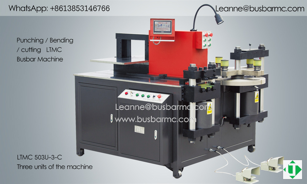
LTMC 503U-3-C three-station busbar machine overview — punching, bending and cutting on one frame (LT / LTMC)
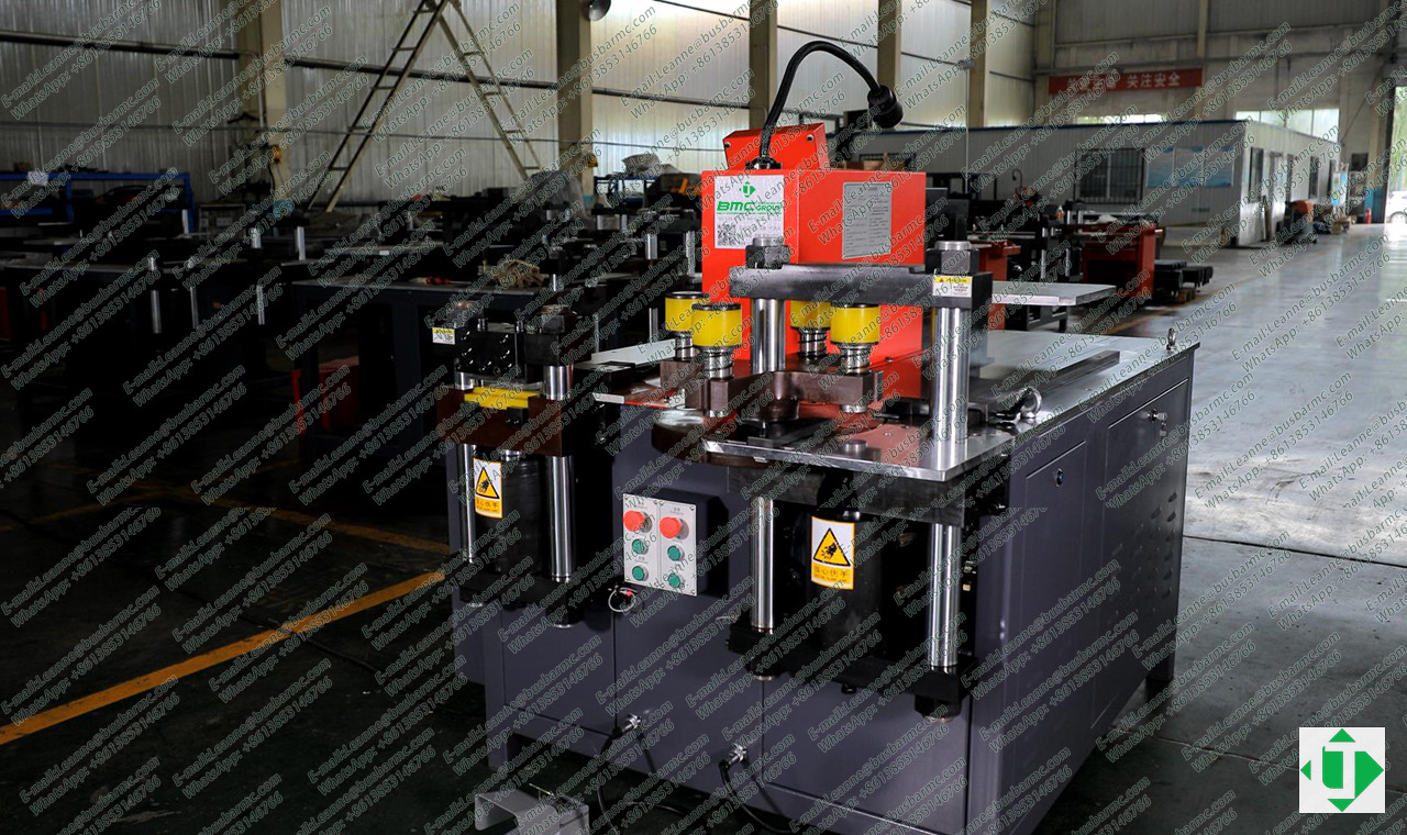
BMC factory view of a multi-station busbar processing machine with turret punch and shear heads (LT / LTMC)
What is a busbar?
A busbar is a flat conductive bar—usually copper or aluminium—that distributes current inside panels, switchgear, transformers, and busway. Versus cable harnesses, busbars give lower resistance path geometry, cleaner cabinet layout, and repeatable bolt patterns when hole positions and bend angles stay within drawing tolerance.
| Material | Typical reason to choose | Processing note |
|---|---|---|
| Copper busbar | High conductivity, mechanical strength, long-term stability | Baseline dies and springback tables |
| Aluminium busbar | Lower mass and material cost | Often larger springback compensation and minimum inside radius; do not copy copper bend programs without trial |
Selecting copper vs aluminium also drives tonnage, die clearance, and surface care (oxide, scoring).
What is a busbar machine?
A busbar machine turns raw bar stock into finished conductive parts by combining:
- Cutting / shearing — finished length and square cut face
- Punching — round, oblong, rectangular, square holes (and often chamfer)
- Bending — flat (horizontal) bends, edge / vertical bends, U / Z / L shapes; optional emboss or twist with extra dies
Dedicated cutters, punches, or bend centres exist. A 3-in-1 busbar machine packs all three into one footprint for SME panel shops. CNC / servo options add stored lengths, hole coordinates, and bend templates via HMI / PLC. Automatic lines add feeding and nesting for high volume.
What materials and sizes can it process?
Modern hydraulic busbar machines process copper and aluminium within a published max thickness × max width envelope and a punch diameter range. Force (kN), die set, and hydraulic design must match the hardest job—not only the average bar.
How does a busbar machine work? (HowTo)
Workshop process (numbered)
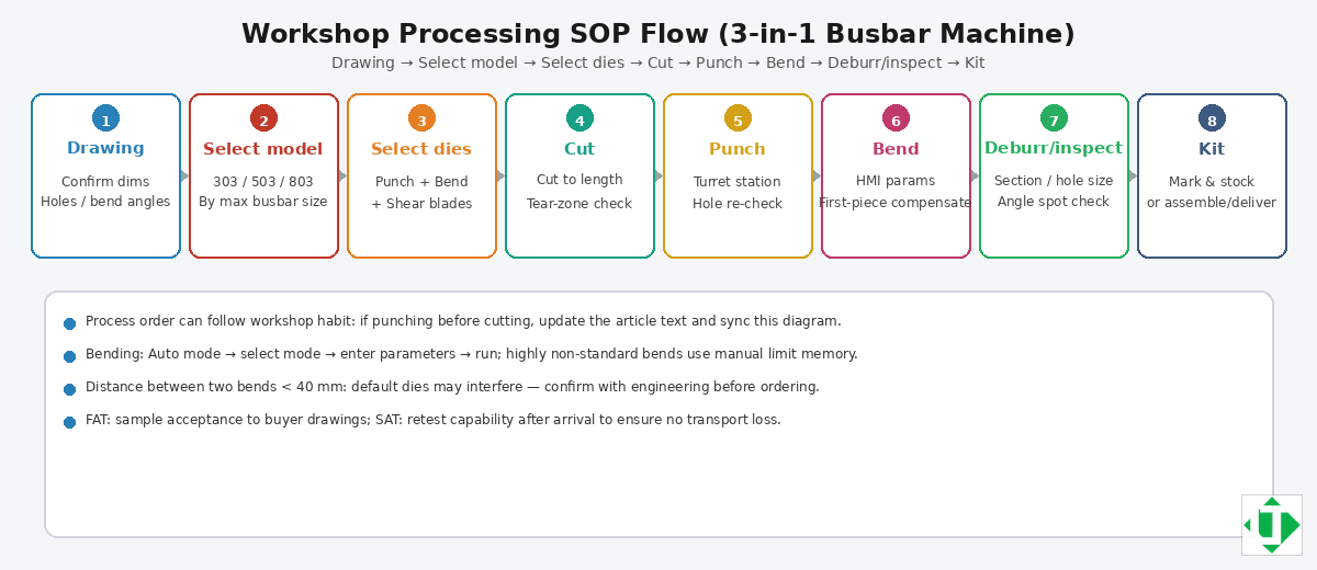
Workshop SOP flow: Drawing → Select model → Select dies → Cut → Punch → Bend → Deburr/inspect → Kit
- Confirm drawing — material, temper, length, hole map, bend sequence, tolerances.
- Select model class — map max width×thickness and hardest hole/bend to 303U-3-C / 503U-3-C / 803U-3-C.
- Select dies / moulds — punch shapes, bend radii (e.g. R3/R5/R10/R80), U-die; check close-bend spacing.
- Feed and position — clamp bar; use scales, stops, or CNC/servo positioning.
- Cut to length — shear unit; inspect cut face and tear zone.
- Punch holes — turret or die change; verify first-article coordinates.
- Bend — select flat vs edge bend mode; apply springback compensation; check angle.
- Deburr, inspect, kit — length, holes, angles, surface; mark and package.
Station physics in one sentence each
- Cut: hydraulic shear + alloy-steel blades → length + controlled tear zone.
- Punch: aligned upper/lower dies + tonnage margin → hole size/position.
- Bend: closed die set + angle control + springback table → installable geometry.
Key working units
1) Cutting / shearing unit
The cutting unit sets finished busbar length. A dual-pillar (or equivalent guided) shear head plus stable hydraulics aims for a flat face and limited tear zone. Published workshop targets often cite tear zone under \~25%—treat as a FAT measurement, not marketing copy.
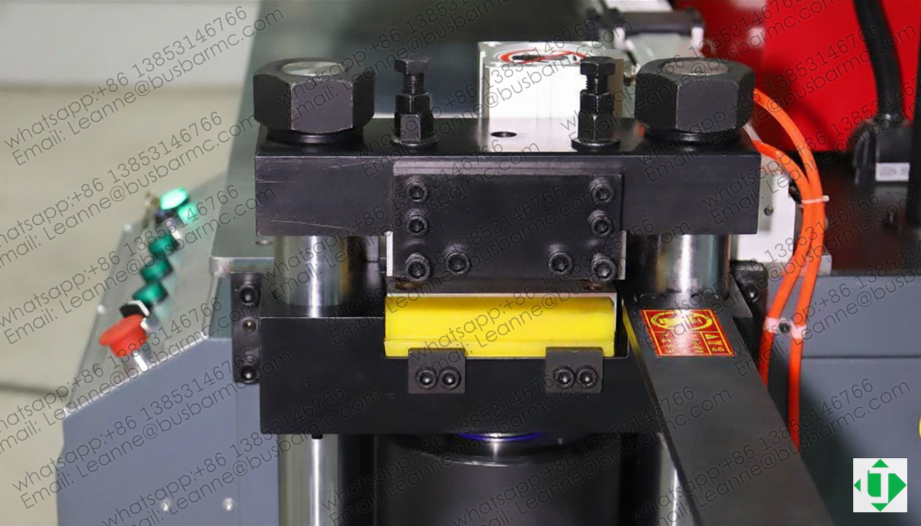
Cutting (shearing) unit close-up: guided shear head and pressure pad (LT / LTMC)
2) Punching unit
The punching unit creates installation holes. Many 3-in-1 designs use a six-station turret so round/oblong (and other) dies stay centred and changeover is fast. Quality = die alignment + clearance + enough tonnage for thickness and hole diameter.
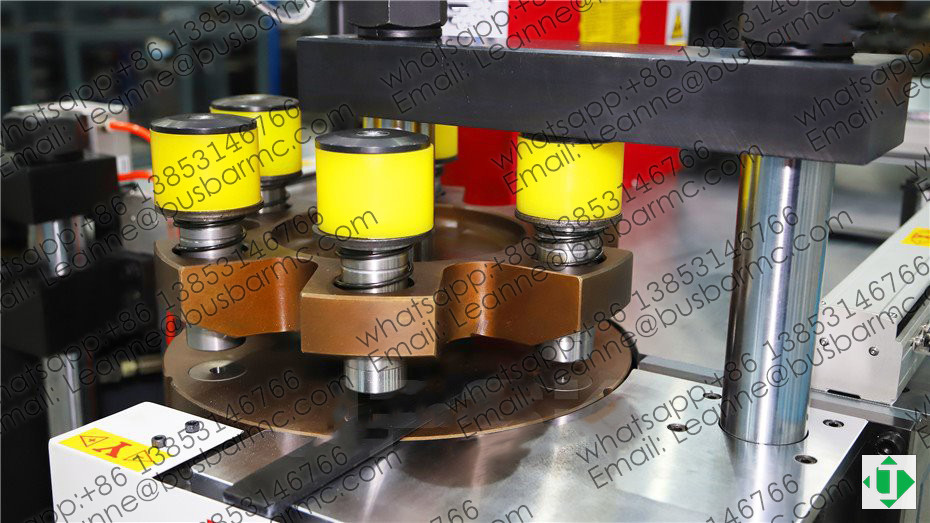
Punching turret unit with multi-station dies and strippers (LT / LTMC)
Illustrative starter die families (confirm on order): round Ø7/9/11/13/17; oblong Ø11×15, Ø13×18, Ø17×21.
Published punch ranges (LT public tables): 303 Φ4.3–Φ25 · 503 Φ4.3–Φ30 · 803 Φ4.3–Φ34.
3) Bending unit (flat vs edge bend)
The bending unit forms the final shape. Typical capabilities:
- Flat / horizontal bend — bar lies flat; common L / U / Z offsets
- Edge / vertical bend — bend in the thickness plane; capacity often tighter (e.g. published vertical sizes 10×100 mm on 303; 12×120 mm on 503/803)
- Mode library via Siemens PLC + HMI (auto: select mode → enter length/thickness/angle; manual: set stroke limits for unconventional bends)
- Default radii often R3, R5, R10, R80 or R50 plus U-shape
- Close bends with spacing under \~40 mm need engineering review
Published accuracy on product pages: about ±1° with repeat around ±0.5° (verify on OA/FAT).
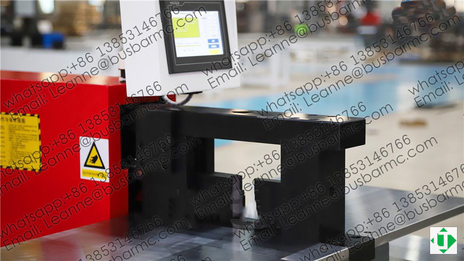
Bending unit with worktable and HMI panel (LT / LTMC)
Copper vs aluminium springback: aluminium usually needs larger compensation and larger minimum inside radius. Keep separate springback tables; never paste copper programs onto aluminium without a trial bend.
4) Hydraulic system, HMI / PLC, dies
- Three motor–pump groups on many U-3-C machines so punch, cut, and bend can work simultaneously or sequentially
- Siemens PLC on bending + HMI / mobile panel; default voltage often 380 V / 50 Hz (Australian shops commonly order 415 V / 50 Hz; other customs include 400 V 60 Hz, 220 V 60 Hz if declared at order)
- Dies / moulds decide real capability: punch shapes, bend radii, embossing, cutting blades, optional twist
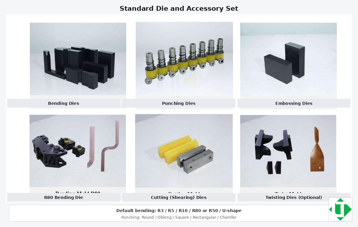
Standard die and accessory set with English labels (bend radii, punches, emboss, cut, twist option)
Finished samples: cut + punch + bend together
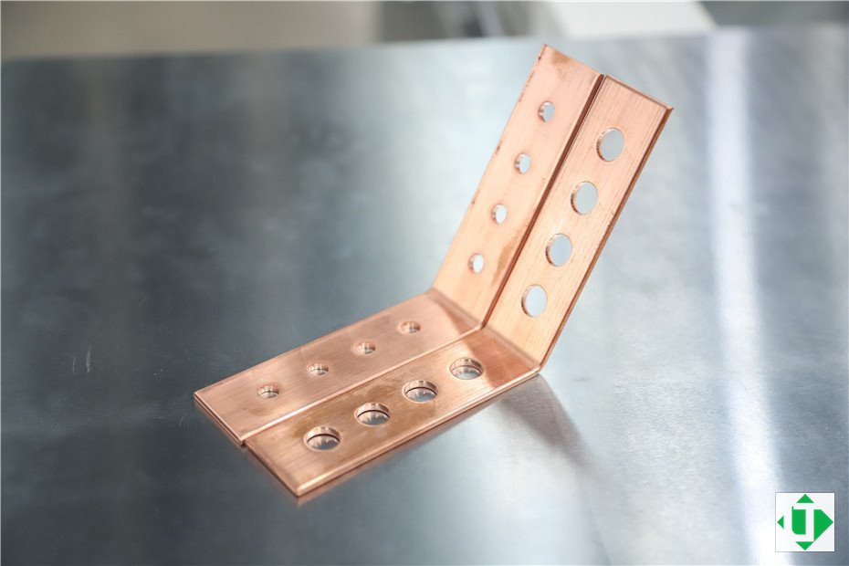
Copper busbar samples after cutting, multi-hole punching and L-bend (LT / LTMC)
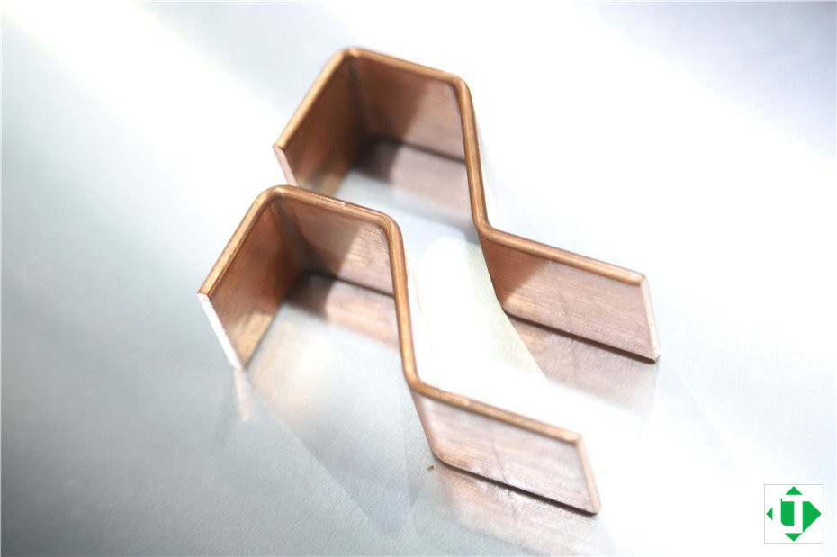
Copper Z / offset bend samples from the bending station (LT / LTMC)
These samples show why the three stations are one process family: length, hole map, and bend geometry must land together for cabinet fit.
Types of busbar machines
| Type | Best fit | Trade-off |
|---|---|---|
| Manual / portable hydraulic tools | Field repair, tiny mods | Low repeatability for production |
| Hydraulic 3-in-1 (three-station) | SME panel shops, mixed jobs | Manual transfer between stations |
| CNC-assisted 3-in-1 (HMI/PLC/servo stops) | Repeat batches, stored bend/punch templates | Still one-frame capacity ceiling |
| Dedicated punch / shear / bend centres | High throughput per process | More footprint and handling |
| Automatic CNC busbar line | High volume, nesting, minimal handling | Higher CapEx and floor space |
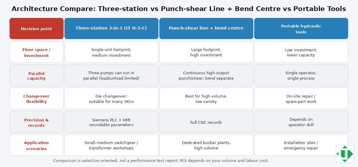
Architecture compare: three-station 3-in-1 vs punch–shear line + bend centre vs portable tools
3-in-1 vs dedicated / CNC line (decision cues)
- Choose 3-in-1 when one compact footprint must cover cut+punch+bend and monthly volume is mixed/SME.
- Choose dedicated stations or a CNC line when hours/day of punching or shearing justify separate capacity, nesting software, and automated transfer.
Why accuracy matters
| Process problem | Typical cause | Machine-side control |
|---|---|---|
| Wrong cutting length | Manual measure / stop slip | Shear stop, scale, or CNC length |
| Hole position deviation | Marking/drill error | Punch turret + positioning ruler / servo |
| Inaccurate bend angle | Operator-only feel | PLC mode + springback table + FAT |
| Slow model changeover | No stored templates | HMI recipes for recurring cabinets |
| High rework | Unstable manual process | Integrated stations + first-article check |
Incorrect length blocks cabinet fit; hole deviation blocks bolts/terminals; bad bend angles collide with breakers, insulation, or structure.
Model selection — LT 303U-3-C / 503U-3-C / 803U-3-C
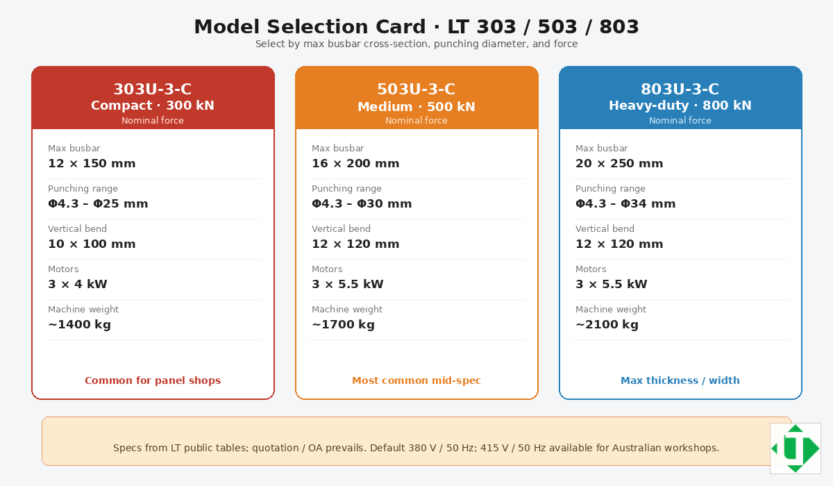
Model selection card: LT 303U-3-C / 503U-3-C / 803U-3-C (force · busbar · punch)
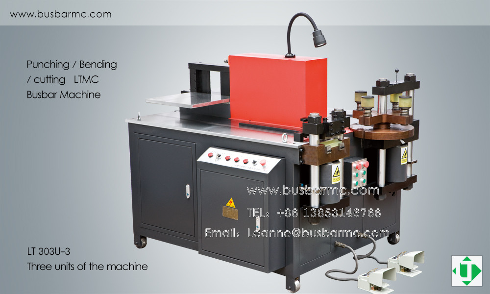
LT 303U-3 class three-unit busbar machine overview (LT / LTMC)
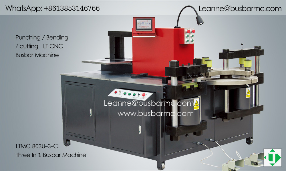
LTMC 803U-3-C three-in-1 busbar machine overview (LT / LTMC)
| Entity | 303U-3-C | 503U-3-C | 803U-3-C |
|---|---|---|---|
| Nominal force (kN) | 300 | 500 | 800 |
| Punching diameter (mm) | Φ4.3–Φ25 | Φ4.3–Φ30 | Φ4.3–Φ34 |
| Max thickness (mm) | 12 | 16 | 20 |
| Max width (mm) | 150 | 200 | 250 |
| Max shear thickness / width (mm) | 12 / 150 | 16 / 200 | 20 / 250 |
| Max horizontal bend width / thickness (mm) | 150 / 12 | 200 / 16 | 250 / 20 |
| Max vertical bend size (mm) | 10×100 | 12×120 | 12×120 |
| Motor power | 3×4 kW | 3×5.5 kW | 3×5.5 kW |
| Bend precision / repeat (published) | ±1° / ±0.5° | ±1° / ±0.5° | ±1° / ±0.5° |
| Approx. mass (kg) | \~1400 | \~1700 | \~2100 |
Quick selection: 303 ≈ 12×150 / Φ25 class · 503 ≈ 16×200 / Φ30 · 803 ≈ 20×250 / Φ34.
Selection checklist (before RFQ)
- Material (Cu/Al) and temper
- Max width × thickness (and longest bar handling)
- Hole list (diameters, oblong, count per bar)
- Bend list (flat vs edge, U/Z/L, close spacing)
- Tolerances and monthly volume
- Factory voltage / frequency and HMI language
- Mould package + spare blades/seals
- FAT sample drawings
What to send before buying
| Information | Why it matters |
|---|---|
| Copper or aluminium | Tooling, clearance, springback |
| Max thickness / width / length | Capacity and table design |
| Hole sizes and drawings | Punch die package |
| Bending angles and direction | Flat vs edge dies, mode library |
| Daily / monthly quantity | 3-in-1 vs line |
| Factory voltage and destination Australian port | Export electrical build |
| Destination country | Docs, packing, after-sales |
Engineering drawings shorten quotation cycles and prevent undersized tonnage or missing dies.
FAQ
What is a busbar machine?
Industrial equipment that cuts, punches, and bends copper or aluminium busbars for electrical cabinets, switchgear, transformers, and distribution systems.
How does cutting, punching and bending work on one machine?
A 3-in-1 / three-station frame hosts a shear unit, a punch unit (often a multi-die turret), and a bend unit with shared or independent hydraulics. Operators (or CNC stops) position the bar; each station applies hydraulic force through dedicated dies.
Can one machine cut, punch and bend copper busbars?
Yes. Models such as the LT 303U-3-C / 503U-3-C / 803U-3-C integrate all three. Throughput still depends on loading, fixtures, and whether stations run in parallel.
What copper thickness can a busbar machine process?
It depends on model class. Public LT tables list about 12 mm (303), 16 mm (503), and 20 mm (803) max thickness—always confirm width and hole/bend limits on the quotation.
Flat bend vs edge (vertical) bend — what is the difference?
Flat bend forms the bar in the wide plane; edge/vertical bend forms in the thickness plane and usually has a smaller published envelope (e.g. 10×100 or 12×120 mm class).
How do I choose between a 3-in-1 and separate machines?
Use 3-in-1 for compact workshops and mixed jobs. Use separate stations or a CNC line when volume, nesting, or dedicated accuracy justify CapEx and floor space.
What about springback on aluminium?
Aluminium typically needs larger springback compensation and careful minimum radius. Keep material-specific tables and verify on first article.
What information should I provide for a quotation?
Material, max size, hole and bend drawings, volume, voltage, destination Australian port (if known), and preferred automation level. See the table above.
Where is public product information?
https://www.busbarcnc.com/ — treat order acknowledgment + FAT samples as the customer-facing source of truth when public pages differ by region.
Talk to LT about a machine for your Australian workshop
For a quotation, FAT samples, tooling lists or sea freight to Australian ports (Sydney, Melbourne, Brisbane, Fremantle or Adelaide), contact LT at [email protected] or +86 13853146766 (WhatsApp), or use the contact page. Public product information is on busbarcnc.com.
Source and revision
- Prepared for: Australian switchboard builders and panel shops, published on busbarcnc.com
- Brand: LT / LTMC · models 303U-3-C · 503U-3-C · 803U-3-C
- Figures: LT / LTMC workshop photos and English schematics, hosted on this site
- Note: Confirm capacities, dies and voltages on the order acknowledgment and FAT samples. Electrical clearances in the finished assembly follow the switchgear design and AS/NZS 61439, not the machine alone.